Cleverscope | Oscilloscopes
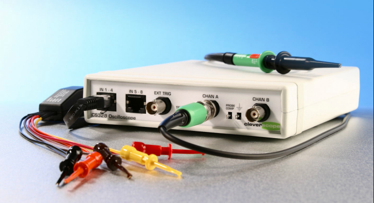
Cleverscope CS328A Mixed Signal Oscilloscope and Signal Analysis System
Now includes NABL Calibration Certificate.
Cleverscope CS328A is a high-resolution, mixed-signal oscilloscope and signal analysis platform designed for in-depth embedded systems debugging, control system validation, and frequency/spectrum response analysis. It combines oscilloscope, spectrum analyzer, signal generator, and a mathematics engine into a powerful PC-connected tool ideal for engineers, educators, and researchers..